Hi,
We are working with AB-CompactLogix L32E controller including Compact I/O 1769-IF8 analog input module. We have been configure 1769-IF8 module as engineering units (Min 4000 to Max 20000).
At the analog input side we have connected Non-Loop powered 4-20mA Amplifier as per 1769-IF8 wiring drawing (Iout+ to Iin+ and Iout- to V/I in-). The amplifier successfully generate the 4-20mA signal without oscillation at the output terminal. But the controller shows only 3200 (engineering unit) value with no change.
We don’t know what’s the problem is. Also we had double check our input wiring connection and module configuration there is nothing wrong. Apart from that please give us solution to eradicate this problem and give any suggestion.
Here are a few clues: 1. Check the power supply voltage that is supplied to the module. As you do so, did you count cards starting at zero for the CPU? 2. What position is the Program/Run/Remote Run keyswitch in? 3. Are other cards being recognized by the CPU or is this the only one tested thus far? 4.Which point are you looking at- did you remember to count starting at zero? 5. Are you looking at the point with the RA ControlLogix Studio 5000 software also? Did you configure it for a different type of protocol than the RS Classic Linx yet use the same cabling?
Ordinarilly, failing the above steps I would point to https://support.inductiveautomation.com and suggest reading the support policy first. In this case, you should consider the Rockwell Automation site support telephone numbers if the above does not help. Do not panic- the symptom described is usually resolved without sending any hardware back to Milwaukee. It typically has to do with setting up the Studio 5000 or the current loop ( which might be interpreted as backward- yet you should talk to Rockwell about the polarities ).
I was going to suggest trying over to PLCTalk, as there are a LOT of helpful and knowlegable people over there.
But then I see you already did. 
Give one solution - PLCS.net - Interactive Q & A
Thanks Jordan- It appears that a Mr. Bernie Carlton already suggested the negative line be connected to ANLG COM ( in addition to V/I in- ).
However:
"Hi ken,
yeah, it’s right but that is full range engineering units for 3.2mA to 21mA. we want only 4 to 20mA signal that’s the reason for choosing 4000 to 20000.
And one more think, I want to inform you. We had already get the output from plc properly by our old amplifier pcb board, which contains only normal components. but now we have go to new pcb board. here we replaced some normal components into SMD components.
After that, we are struggle to get the output from plc." Means that there could be some intermittent problems on that new Printed Circuit Board. Either the circuit traces are not wide enough, the components not rated for the correct heat dissipation, or most likely of all- the soldering temperature was incorrect ( which might result in a crystallized or intermittent solder joint ). If the PLC cannot read a good signal using that ANLG COM for the negative as well as the V/L in-, then the other questions about software and count issues may still help.
Consider disconnecting your existing process and connecting a battery powered loop simulator. With a milli-ammeter in series to verify. Prove your input module works as documented before looking elsewhere.
Also, keep in mind that the IF8 is a single-ended non-isolated input module. The sending device must use the same DC common, or at least keep the actual voltages on the + and - pins within 10V of the module’s analog common.
BTW, if the module is sending a value that is below your minimum engineering range, it is a pretty good hint that you are getting less than your minimum 4mA to the input pin.
https://www.rockwellautomation.com/en_NA/support/overview.page (Change the NA to your Country Code or just enter …com/en for English & browse to match ) should give you the best clues if you are sure that you are looking at the correct circuit card NUMBER and point NUMBER of a properly-configured system*. Yet you could spend much more time getting an answer there than checking the input and connections as described above ( by Mr. Turmel, Mr. Carlton, and myself ) to ensure that you have:
4-20 Ma applied with the connection in series through the card- If the simulator can do it you know the problem is the new SMD card or battery/power supply in a different one.
The correct Ground references- we all talked about that wiring in re: Analog Common, not just VL in-.
*Properly configured includes RUN mode, virtual controller setup, Etc. thus Rockwell Automation is mentioned because there could be software and/or licensing issues involved. If you have seen the input of some other card, or some other card output- this is doubtful.
Consider showing the complete schematic of your IF8 module as currently wired up.
Also consider sharing more information about the device connected to the IF8 card. Any documentation you can link to or share may also help us understand what you trying to do.
Since it seems that someone earlier mentioned ‘matching impedances’, which generally applies only to alternating current and audio (colon not emoji)
Consider telling us also about both the 4-20 Ma device you are using and the source of DC supply in terms of both voltage and current capacity.
What the impedance question may have been searching for is this: There is a source and a load resistance involved in all DC circuits. If the source current supply is insufficient ( for example, a string of hearing aid batteries in series ) for the expected load ( for example, the starting motor of a vehicle )- then the source voltage may look good until it is actually connected. The source voltage is typically assumed to be under 48 volts DC, and the current flowing in the circuit depends on the impedance which is a construct of resistance and reactance. In a local DC circuit, the reactance becomes insignificant. Using Ohm’s Law, we should get a resistance value that would be the effective impedance for a DC circuit. Many power supplies also add A.C. ripple, which can have big impact for sensitive circuits.
thank you for reply jlivingston, as you above mentioned points are checked that’s clear. And also I’m go through the link https://support.inductiveautomation.com, there is no search are match to my questions.
yes jlivingston, we are also doubted about that components used in the PCB board. since we have been checking the each component datasheets.
your comments are already checked one.
please find the our referenced attached wiring diagram.
have you any documents related to how can matching the impedance.
I read your original post, and I understand.
This is not impedance matching. Impedance matching is in audio and radio applications to minimize the chance of burning out an amplifier due to reflected power.
What you are looking to do is ensure that your current source can supply enough current over a wide range of resistance and still be accurate. This is not the same thing.
According to the IF8 spec, the input impedance for a current input is 250 ohms. Many loop circuits are designed for a max of 500-600 ohms to take into account wire resistance. I have used circuits similar to this on the bench for testing.
Try your device out though a range of resistances to see if it remains stable.
Is the connecton from Sensor/Transmitter Supply (-) to the IF8 "ANLG Com" terminal present? (Bottom right wire.)
sorry, I mentioned in the wiring diagram is wrong. Actually that below one (Differential current transmitter) from where that arrow indicates.
Is the connection from Sensor/Transmitter Supply (-) to the IF8 “ANLG Com” terminal present? (Bottom right wire.)
No, that connection is not applicable for our differential current transmitter.
Thank you and i’ll try it.
That connection is absolutely required, for all of the transmitter types shown in that drawing. The IF8 accepts a differential input, but it is not isolated. Your transmitter power supply must use the same DC common as the IF8 module. See highlighted sections here:
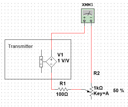
Please look again at figure 2.18. That Analog Common is shown. If you are concerned about adding that extra ground because of a non-isolated power supply, then for temporary use a low-wattage potentiometer ( say, 1/4 watt or less- most are ) variable between 10,000 ohms and 250 ohms ( in that order ) with a fast-blow fuse (.250 amp=250 milliamps or less ) in series between your sensor transmitter supply negative and the ANLG Com terminal for the point that you are using. If you move your pointer arrow down to the differential current transmitter, you will note that the negative supply line does connect to the ANLG Com for a different input. Com means Common, as in common to all inputs.
A separate screw terminal does not necessarily mean a separate connection for Com terminals- yet you may wish to confirm this with power off.

