I am using an HMI that was create by a SCADA engineer using Ignition SCADA.
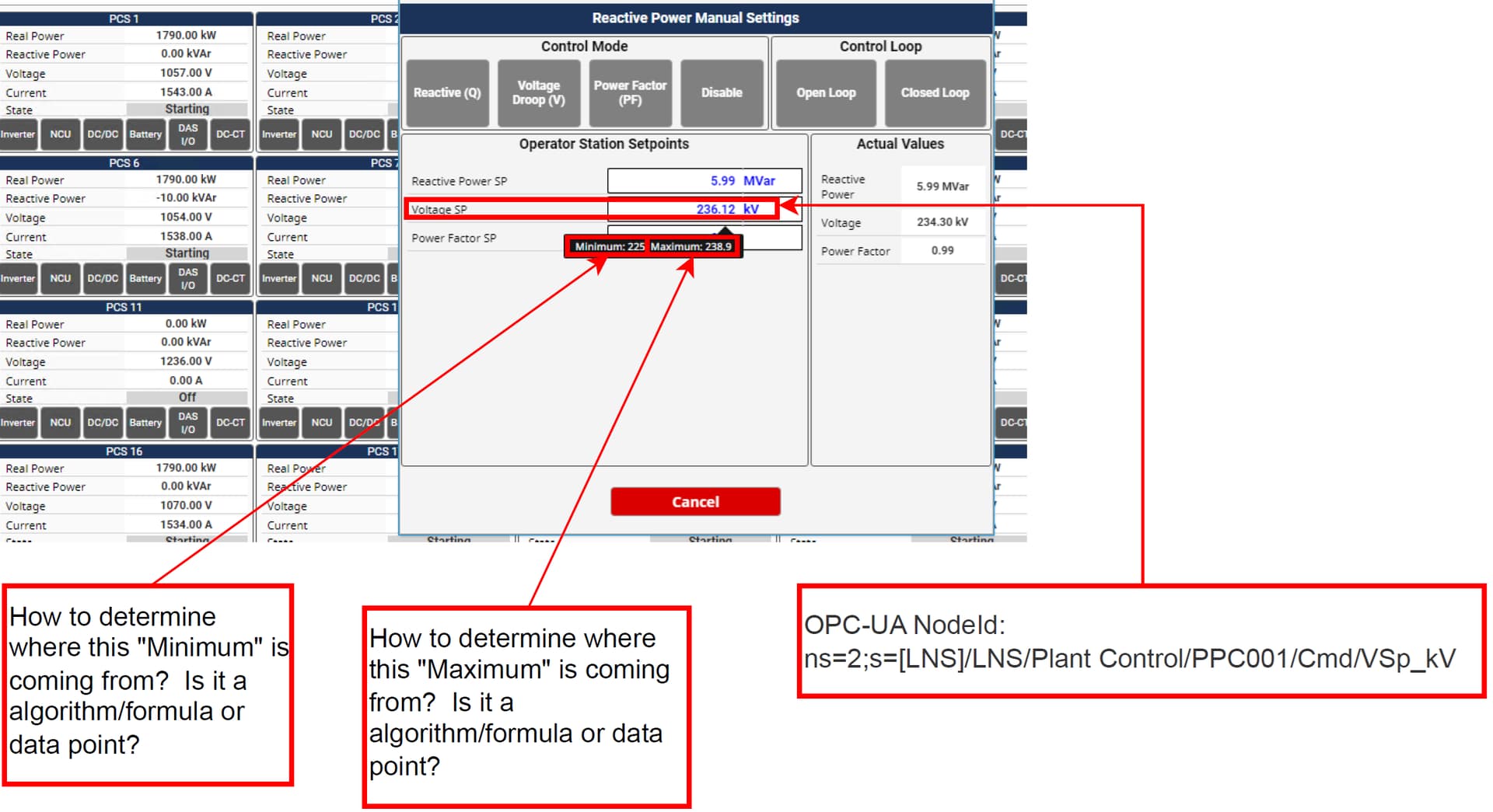
There is something on the “Reactive Power Manual Settings“ HMI dialog that shows “Voltage SP“. When I mouse over this “Voltage SP“ it gives me help tips, in this case it shows “Minimum:225, Maximum:238.9“.
How do I determine where these values come from? Are these values data points or formulas. How can I find this out?
Can this be done by downloading the project locally and opening it in a local VM running Ignition SCADA? How do I go about it?
The only way to know is to inspect the project itself. This appears to have been made by an integrator, and they probably have their own pre-made templates and standards.
Tooltips are part of the meta properties of components and their contents are completely up to the programmer.
First, remove the idea that Ignition behaves like standard HMI's where you load a project file onto the HMI and run that. Perspective lives completely on the Ignition Gateway. Vision does require a launcher, and while it does run an application directly on the client, all the project data lives on the Ignition gateway. The launcher just pulls the latest and runs that.
If you have designer access to the Ignition server that hosts the perspective project, you should only have to download the designer and open the project from there. No need to spin up a VM.
Keep in mind, depending on the agreement you/your company had with your integrator, you may not have a login for designer access.
you see where it says ‘opc-ua nodeid’ that makes me believe this is a tag value and the part after that is the tag that the value is referencing, so in the plc somewhere there is a tag [LNS]/LNS/Plant Control/PPC001/Cmd/VSp_kV. now where it might be in your file system no clue but that is the tag that the value is coming from so if you can find that tag in your plc software and cross refrence it you can see how the value is made or formulated
travisaggiebrown , there is an OPC-UA module and interface with 120,442 data points exposed. I cannot find the “Minimum“ and “Maximum“. I’ve search for “225“, “238“, “Min“, “Max“. I wrote a Python app to scan the server and to dump the NodeId, the type, & value.
I just can find the data point, so I am trying to figure out how the HMI knows the “Minimum“ & “Maximum“. What is the source code behind the “help tip“.
This. Then install the designer, then run it. You'll need to point it at the gateway hosting your project.
Consider watching some of the free videos from Ignition to guide you through this.
From there, you'll need to open the project, find and open the popup view (which I suspect is a generic view) and then drill down to the entry field and inspect the meta.tooltip property.
The popup is likely getting some information from the view that opened it to be able to indirectly bind to either a device UDT or tag folder structure in Ignition. I wouldn't be surprise if the Max/Min were memory tags in said structure with some 'safe' values determined when the interface was made.
it Really depends on who made it, it could be reading that value off of the tag in the opc ua module but then calculating min and max in ignition, it’s hard to say where its coming from without actually looking at the ignition project itself but my guess since only one tag path is specified that its taking the tag value historizing it and then finding a min and max value using some sort of tag historian query binding
To me, it looks like the values might be coming from a tag historian query getting the min and max over recent history. The values don't look like they're coming from the eng range of the tag. Can only know looking at the designer, or alternativelyt at the json of the view
Since this is clearly a PPC interface at a grid-connected PV or BESS facility, is this in the U.S.? If so, you will have a Plant Control Narrative for your NERC-CIP registration. This Plant Control Narrative, along with hopefully a manual, should describe the formulas used.
Presumably you’re looking at where this Q-V response is coming from? If the interconnecting utility provided a droop curve or a setpoint/deadband, I would assume that’s configured in your PPC. If it is displayed in Ignition, I’ve always seen it mapped as tags from a PPC device.
ryan.white (I can reference you with “at“ symbol because it states I am a new user).
I do understand that Inductive University had courses. Right now, I am slammed with courses for AWS and other technologies. I’d just prefer a step-by-step 1,2,3,a,b,c simple text instructions.
I’d really scour for tags with these values first, because I suspect they would come from the PPC. But to figure out exactly where they come from…
You’d need to open your Ignition project with the Ignition Designer software, using administrator credentials.
You need to identify what view this is in. There’s a layer of abstraction in Ignition Perspective between your webpage and views, and views are often nested/embedded within each other. So it may be easy to find based on naming (e.g. “PPC Reactive Power Manual Settings Faceplate”) or it may require some sequential digging and analysis.
You need to find the specific component within that view upon which the tooltip exists. Once you’re in the view in designer, you can usually keep double clicking on the component to drill down to it, or you can explore to it in the project navigator tree.
Once you’ve selected the component, look for the component properties window (usually on the right) and look for the tooltip configuration (a section near the bottom of the component properties). You should see a link icon (indicating binding) for the text property. Click this binding icon and you’ll get a pop-up showing where your text comes from.
You should contact the support department - they can connect to your live system and help you figure out what's going on, assuming you have a support contract on your license.
Just remember all the people helping you so far are unpaid volunteers.