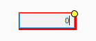
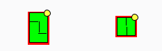
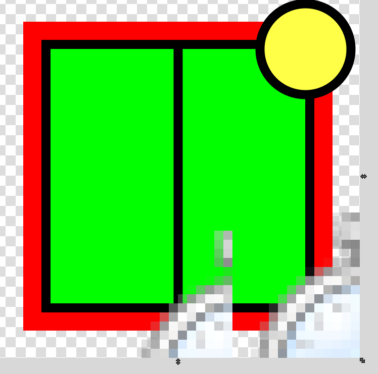
As you can see the ones inside the Vision Client seems the get the lines and the red borders misaligned. I have tried everything i could think off but nothing seems to work.
Does anyone know how we could get everything to look the same inside the Vision Client?
Things to look at: right click and check the layout. Relative will probably be what you are wanting - not anchored. Also, groups don't always behave well when it comes to scaling. If they are grouped, consider ungrouping them and sticking them ungrouped into a template or container.
Yes, maybe i could have been a bit more clear. The small valve we have is like a + with each part of it turned on by a bit innan integer. So we store a integer for it being active and inactive and then use that to turn on the specific lines. My problem is that the lines don’t add up. When i set them in the correct pattern in the designer it seems to move like a pixel or two when viewing in the Vision Client.
The default layout is "Relative", which always scales, often just enough to throw off this sort of thing. Use anchored layout for everything like this. If you must have scaling, use a Paintable Canvas to draw the whole thing on a consistent coordinate system.